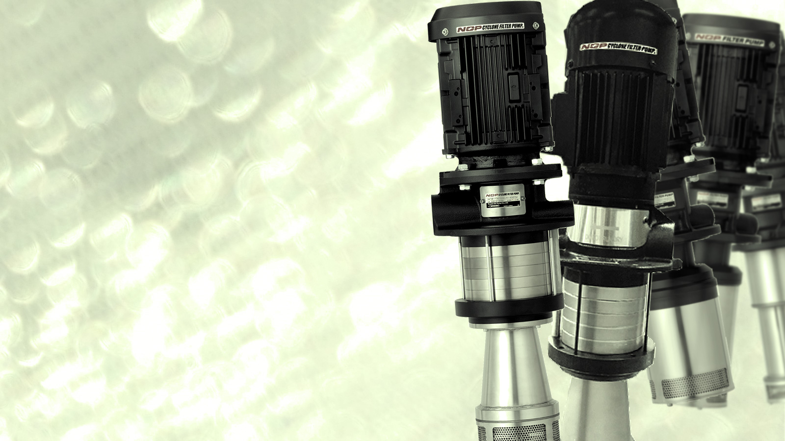
Large Flow Low Pressure Coolant Unit with
Built-in Cyclone Filter
- Cyclone Filter
-
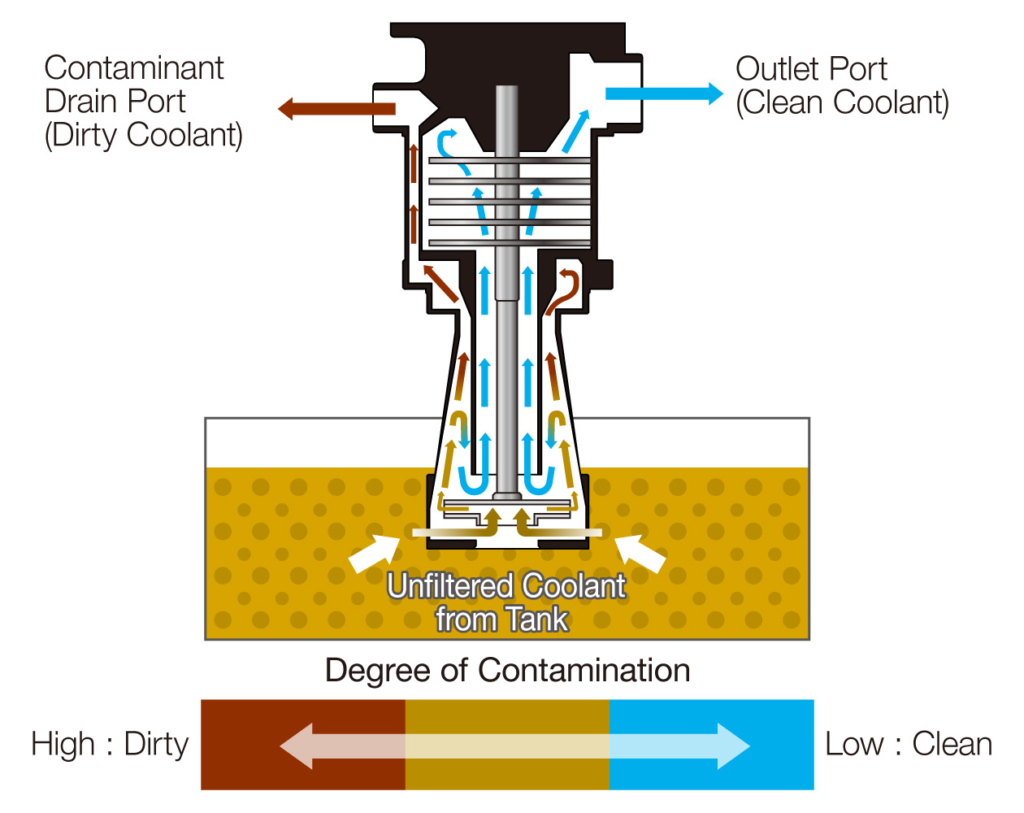
The cyclone system effectively removes sludge from the coolant.
- Impeller Pump
-
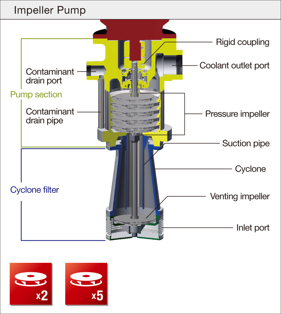
The impellers spin and accelerate the liquid, thereby generating pressure inside the pump. This pump is designed to transfer large flow of liquid.
FEATURES
YTH-CI/GCI
Large Flow Low Pressure Coolant Unit
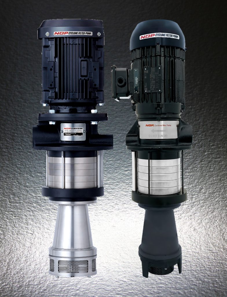
YTH-CI/GCI is designed to deliver large flow at low pressure with built-in cyclone filter. Its compact design enables easy retrofitting to your existing tank of NC lathe, machining center or grinding machine, etc.The large flow also ensures high efficiency in sludge removal, which substantially reduces problems around the tank, such as dimensional deviation of workpieces, clogged plumbing due to excessive accumulation of sludge.
- Total Pump Head: 35–65 m
- Maximum Flow Rate:
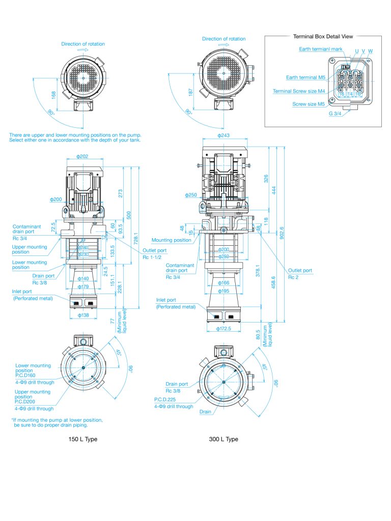
CI 15*C: 150 L/min
CI 30*C: 300 L/min
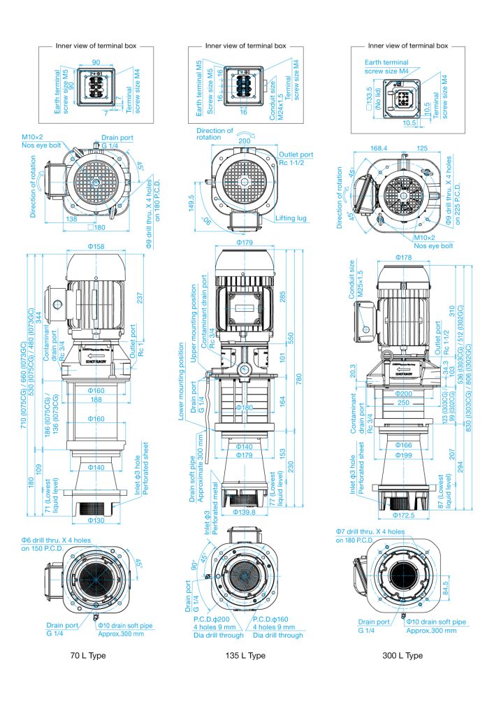
GCI 07*CG: 70 L/min
GCI 13*CG: 135 L/min
GCI 30*CG: 300 L/min
Cyclone Filter
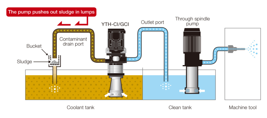
This unique reversed cyclone system can separate clean coolant and dirty coolant inside the pump. Dirty coolant is pushed up through the side surface of cyclone filter by centrifugal force and discharged with sludge. Filtered clean coolant is collected to the center of cyclone filter and boosted up by multiple-stage impellers.
Impeller Pump
YTH-CI/GCI employs impellers whose design is best suited for supplying large quantity of coolant and capable of boosting up pressure with its multiple stage impellers.
- Compatible fluid type
- Water soluble cutting fluids.
- Non-water soluble coolant with kinematic viscosity of 22 mm2/s or less.
- Incompatible with lubricant oils and fuel oils.
- Incompatible with clear water, demineralized water, aqueous solutions and viscous fluids which do not offer rust-protection, corrosive fluids and solvents.
Filter Rating (Nominal value)
| Suction strainer | 3 mm (Solids larger than this must be removed from the tank) |
| Cyclone filter | Water soluble coolant 100 μm: 99.9% (Specific weight 2.7) Straight oil 100 μm: ≧ 80% (Specific weight 2.7) |
Corresponding Chip Type
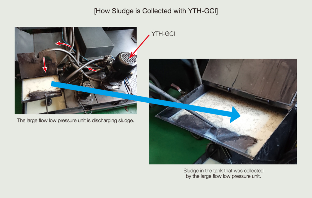
SLUDGE COLLECTION WITH YTH-CI/GCI
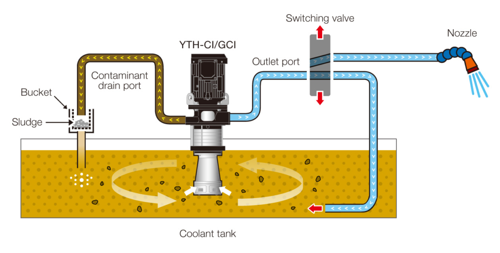
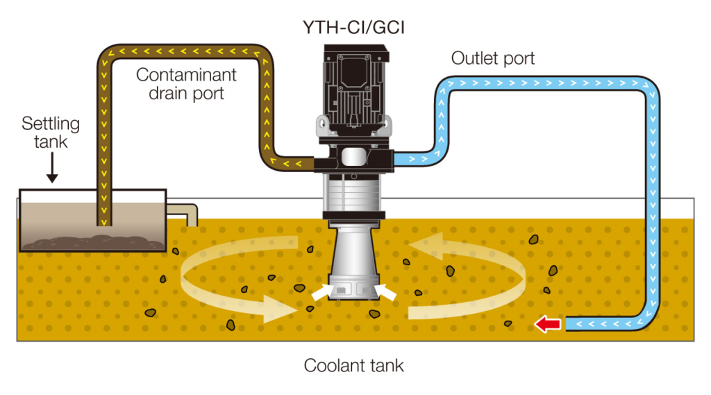
Install YTH-CI/GCI in a way that filtered clean coolant from the outlet port can circulate all around the tank.
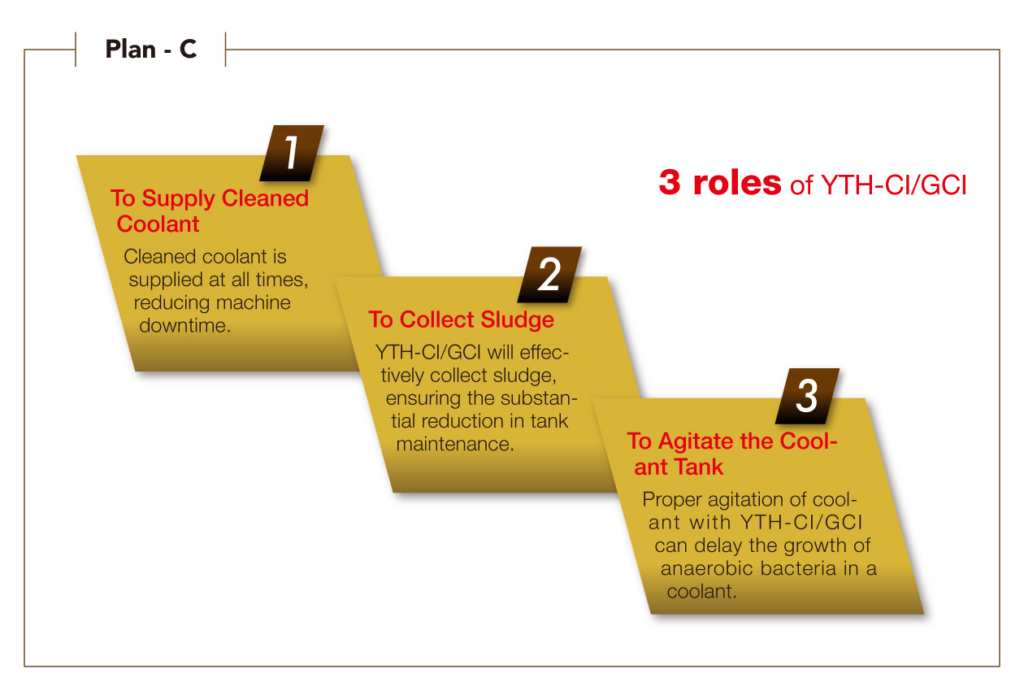
Proper agitation of the tank by following STEP 1 can prevent sludge precipitation in the tank. YTH-CI/GCI can also collect sludge floating in the tank and discharge from the contaminant drain port.
Discharged sludge can be collected with YTH wire mesh bucket or a settling tank.
MODEL NUMBERING SYSTEM
YTH-CI/GCI
MODEL NUMBERING SYSTEM
TOP−YTH ① ② – ③
YTH-CI
| ①Motor Capacity | 1500: 1.5 kW 3700: 3.7 kW |
| ②Motor Type | AC: AC 200/200/220/230V 50/60/60/60Hz 3 phase electric induction motor (IE3) with CE marking |
| ③Pump Capacity* (Impeller Pump) | I155C: 150 L (5 stages) with 50 Hz motor I152C: 150 L (2 stages) with 60 Hz motor I305C: 300 L (5 stages) with 50 Hz motor I302C: 300 L (2 stages) with 60 Hz motor |
YTH-GCI
| ①Motor Capacity | 1100: 1.1 kW 1500: 1.5 kW 3000: 3.0 kW |
| ②Motor Type | W1/R2/W3/W4/R5/R6/W7 See the “MOTOR SPECIFICATIONS” table below for the voltage, frequency, approvals |
| ③Pump Capacity* (Impeller Pump) | I075CG: 70 L (5 stages) with 50 Hz motor I073CG: 70 L (3 stages) with 60 Hz motor I135CG: 135 L (5 stages) with 50 Hz motor I132CG: 135 L (2 stages) with 60 Hz motor I303CG: 300 L (3 stages) with 50 Hz motor I302CG: 300 L (2 stages) with 60 Hz motor |
SPECIFICATIONS
YTH-CI
| Model | Motor Capacity (kW) | Voltage (V) | Frequency (Hz) | Approvals | Flow Rate (L/min) | Total Pump Head (m) | Approximate Weight (kg) |
| YTH1500AC-I155C | 1.5 | 200 | 50 | IE3, CE | 150 | 55 | 43 |
| YTH1500AC-I152C | 1.5 | 200/220/230 | 60 | IE3, CE | 150 | 40 | 43 |
| YTH3700AC-I305C | 3.7 | 200 | 50 | IE3, CE | 300 | 65 | 70 |
| YTH3700AC-I302C | 3.7 | 200/220/230 | 60 | IE3, CE | 300 | 45 | 69 |
YTH-GCI
| Model | Motor Capacity (kW) | Motor Type | Max.Flow rate (L/min) | Total Pump Head (m) | Approx. Net Weight (kg) |
| YTH1100**-I075CG | 1.1 | W1, W3, W4, R5 | 70 | 50 | 24.3 |
| YTH1100**-I073CG | 1.1 | R2, W3, R6, W7 | 70 | 45 | 23.3 |
| YTH1500**-I135CG | 1.5 | W1, W3, W4, R5 | 135 | 50 | 40 |
| YTH1500**-I132CG | 1.5 | R2, W3, R6, W7 | 135 | 35 | 40 |
| YTH3000**-I303CG | 3.0 | W1, W3, W4 | 300 | 45 | 65 |
| YTH3000**-I302CG | 3.0 | W3, W7 | 300 | 40 | 64 |
MOTOR SPECIFICATIONS
YTH-GCI
| Motor Type | Power (kW) | Voltage (V) | Freq. (Hz) | Efficiency Clause | Safety Clause |
| w1 | 1.1/1.5/3.0 | 415 | 50 | IE3 | ISI |
| R2 | 1.1/1.5/3.0 | 230 | 60 | CCC | UL/CSA |
| W3 | 1.1/1.5/3.0 | 200 | 50/60 | IE3 | CE |
| W4 | 1.1/1.5/3.0 | 400 | 50 | IE3 | CE/UKCA |
| R5 | 1.1/1.5 | 380 | 50 | IE3 | GB2 |
| R6 | 1.1/1.5/3.0 | 440 | 60 | CCC | UL/CSA |
| W7 | 1.1/1.5/3.0 | 220 | 60 | IE3 | CE |
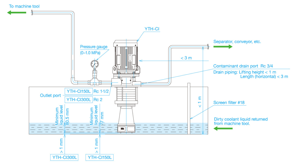
SAMPLE SYSTEM LAYOUT
YTH-CI/GCI
YTH-CI
YTH-GCI
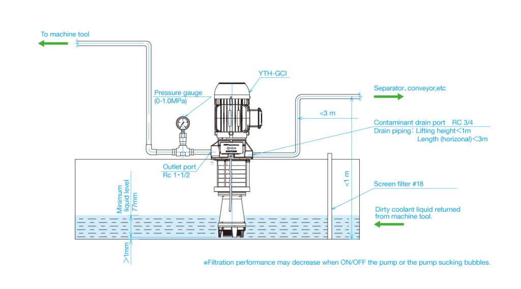
Please be sure to read the instruction manual before use.
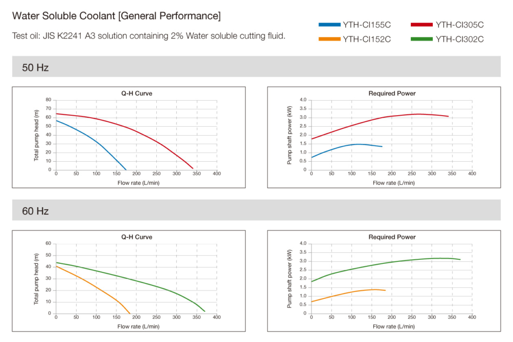
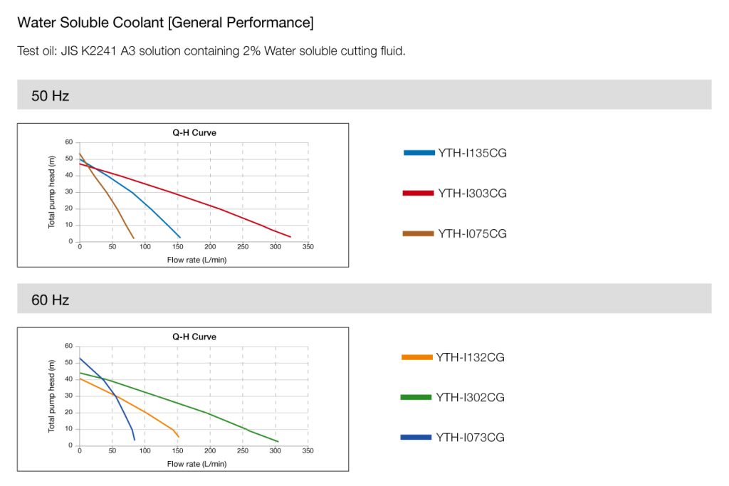
PERFORMANCE CURVES
YTH-CI/GCI
YTH-CI
YTH-GCI
APPLICATION EXAMPLES
YTH-CI/GCI
To Transfer Coolant to an Isolated Clean Tank
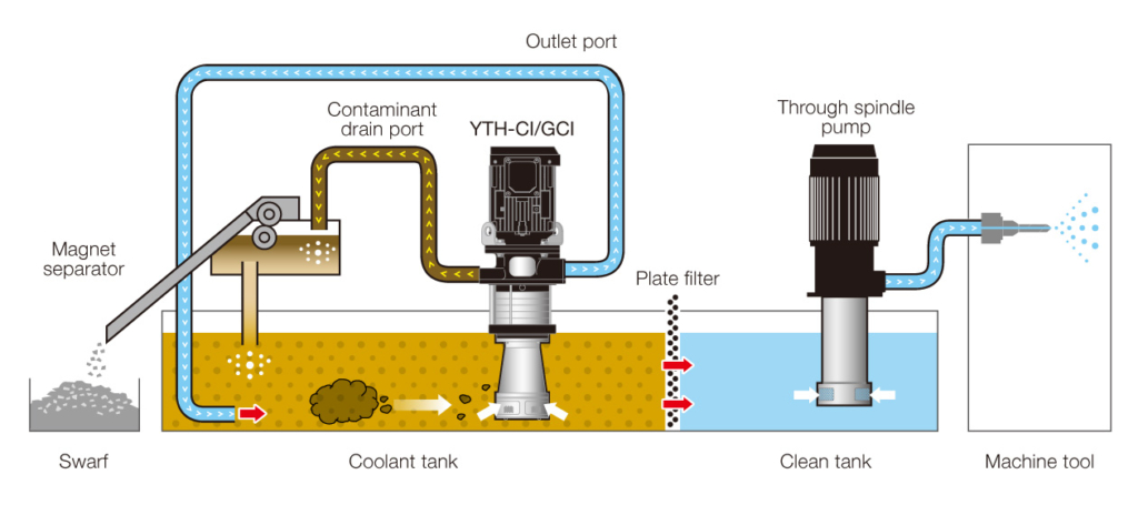
YTH-CI/GCI transfers cleaned coolant from a coolant tank to an isolated clean tank. A plate filter is no longer necessary between the tanks, so the users will be free from the maintenance of plate filter. Furthermore YTH-CI/GCI can separate sludge from the coolant and discharge from contaminant drain port.Discharged sludge can be collected easily with YTH wire mesh bucket, allowing substantial reduction in coolant maintenance.
